How Does CARE Dose4D Work?
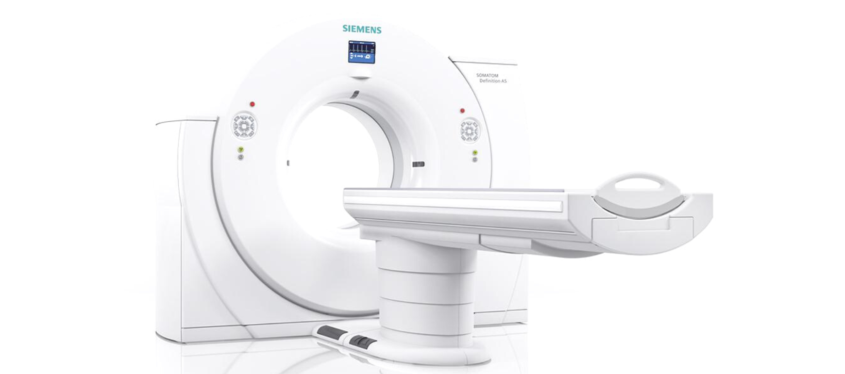
In this post, we’re going to be talking about CARE Dose4D, what it is and how to use it.
Whether you have a Siemens CT Scanner or you’re interested in getting a Siemens CT Scanner, we will provide you with an overview of what CARE Dose4D is all about.
Watch the video above on our YouTube channel as Eric walks you through exactly what CARE Dose4D is and uncovers some of the mystery surrounding CARE Dose4D.
What is CARE Dose4D?
CARE Dose4D is the Siemens version of Tube Current Modulation or Automated Exposure Control. It’s a way for the scanner to predict what the correct tube current output, the mAs, should be in any given position of the scan.
What is Tube Current Modulation?
The concept with tube current modulation is that as we image larger patients or go through thicker parts of the body we’ll increase the tube current, or mAs, to account for the additional tissue or body that we need to penetrate. As we go through smaller or thinner sections of the body, we can decrease the radiation dose.
What are the benefits of using CARE Dose4D?
Benefit 1: Ideal Radiation Dose
The first benefits of using CARE Dose4D or other automated exposure control options is that the radiation dose delivered to the patient is going to be the most appropriate dose for that patient.
Benefit 2: Consistent Image Quality
The second benefit of the Siemens CARE Dose4D option is that we can create consistent image quality within the patient and from patient to patient. For example, if we have an adult abdomen protocol that we’re using, we want to make sure that we have consistent images for 100lbs patients as well as 300lbs patients and everything in between.
We want to create consistent image quality and CARE Dose4D is a tool that helps us do that.
An Illustration of How CARE Dose4D Works
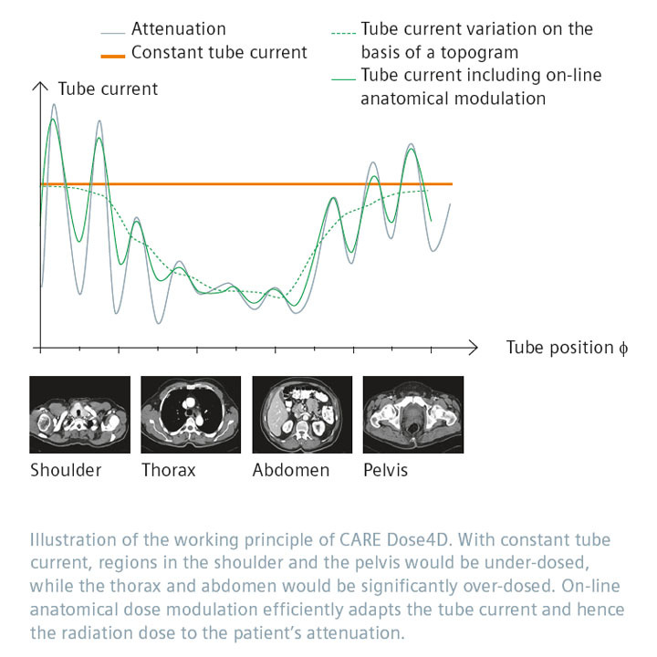
To the left, we have a graphic showing how CARE Dose4D works.
As we scan through the body, the tube current is going to modulate in the X and Y position. The modulation is represented by the peaks and valleys that we see in the illustration.
As an example, as we go through an anterior projection of a patient, we may use more mAs and as we go through a lateral projection, we may use less mAs.
The tube current can actually increase and decrease as the tube is going around the patient.
In addition to that, we also have modulation in the Z direction or the Z axis, when we’re scanning through the patient. As a result, we might use more mAs going through the abdomen and pelvis than we would through the chest, for example.
How Do We Use CARE Dose4D?
When using CARE Dose4D, we need two different parameters in order for the system to be able to calculate what the mAs should be as we scan through the patient. Those two parameters are:
- The image quality reference parameter, which for Siemens is called the quality reference mAs.
- The other thing that we need is the scout or topogram.
How the dose is going to modulate through the patient is based on the topogram and the set point of the quality reference mAs.
How is a Topogram Used for CARE Dose4D?
A topogram is used to allow the system to calculate the size-shape model of the patient to determine how big is the patient. Depending on the software version on your CT scanner, that’s going to change how the topogram is used. Older versions of Siemens software use two topograms to calculate the size-shape model. Newer versions use only one topogram, so be aware that the topogram can be used differently in these calculations based on the software version that you have. However, the concept is going to remain the same.
What is Quality Reference mAs?
The quality reference mAs is the mAs that we would give to a patient if we were to use a fixed technique for an average sized patient. CARE Dose4D defines an average sized patient as 75 kilogram.
CARE Dose4D is going to modulate up and down based on that midpoint. What you should be doing when you set your quality reference mAs is to set it for the mAs that you would give to an average patient for that specific protocol.
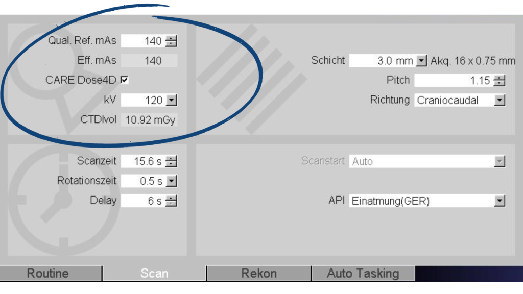
In the above screenshot from a Siemens CT scanner, you can see where we enter the quality reference mAs value. We have our CARE Dose4D turned on and our quality reference mAs is set at 140. Based on that setting of 140, it’s going to give you a prescan CTDI.
That prescan CTDI is going to change for each patient after you perform their scout. The system is going to give you a different value specific to that patient based on what your quality reference mAs is set at.
Once you set your quality reference mAs for the protocol, it should not be routinely changed. This number should stay consistent from patient to patient because the whole point of CARE Dose4D is to modulate the dose up and down based on the attenuation that is seen in the scout for the patient.
An Important Reminder on Patient Positioning
When you’re doing your scout, you want to make sure that you isocenter your patient, getting them right in the center of the gantry as best as you possibly can, because that’s going to affect the size-shape model of the patient.
For example, let’s say you’re doing an AP topogram. If you have the patient really high in the gantry and they’re really close to the x-ray tube, they’re going to appear much larger than what they actually are. The dose is going to modulate up thinking that the patient is larger than they are and you end up giving the patient more dose than what they would otherwise get. The same can happen if they’re too low. They’re going to appear smaller than what they would normally appear, and the dose is going to be lower than what it should be.
You want to make sure that you’re getting that patient isocentered as best as you possibly can in the gantry, so that CARE Dose4D can apply the appropriate amount of mAs for the patient.
Be Aware That There's No Upper Limit
One of the other nuances to recognize with CARE Dose4D is that there’s no upper limit to the amount of mAs that you apply to the patient. The only limit is the power of the x-ray tube itself. With CARE Dose4D, you’re setting a midpoint and then modulating up and down from there.
Looking at the prescan CTDI is really important because you could end up in a situation where you’re giving the patient a higher dose than what they should get. You should be able to tell by looking at the prescan CTDI if that looks normal for the size of patient. Develop a habit particularly on a Siemens scanner of looking at that prescan CTDI to make sure that your dose isn’t modulating too high or potentially too low as well.
The Siemens guidance documents on CARE Dose4D say that you don’t need to create large patient or obese patient protocols. The reason for this is because the tube current is going to modulate up based on what it’s seeing in the scout and the quality reference mAs. You don’t need to increase the quality reference mAs. You don’t need to create a different protocol for large patients because it should all be taken care of by just using CARE Dose4D the way that it is out of the box.
CARE Dose4D Configuration Settings
One additional aspect to learn about CARE Dose4D is the configuration settings that dictate how strong or weak the CARE Dose4D is applied to patients. To find this area, go to Options, Configuration and then Examination. Once there, click on the dose card, you’re going to see this screen pop up.
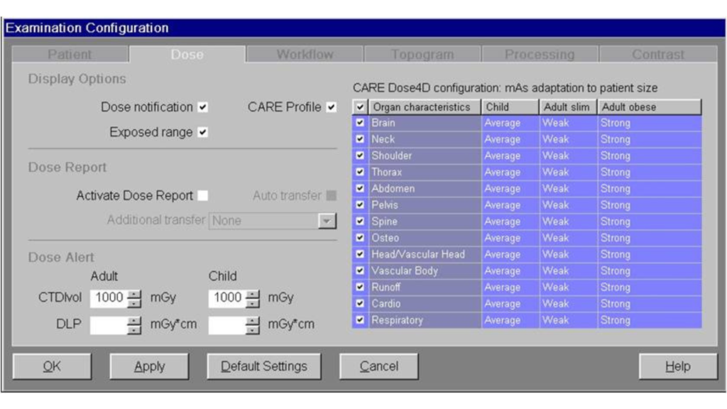
On this screen you have dose notifications and what the dose alert value should be. This is also where you find the CARE Dose4D configuration. You’ll see there are three columns – child, adult slim and adult obese along with settings for each body part. Oftentimes these will be set to average across the board. Everything can be set to average, but they can be changed to average, weak, strong, or very strong.
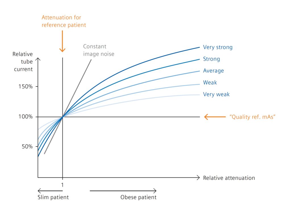
In the above graphic, you can visually see what very strong, strong, average, weak, and very weak looks like for our reference patient as well as for slim and obese patients. The midpoint is for the attenuation of the reference patient. As we get to larger and larger patients, we can see how the strength of CARE Dose4D is applied. In addition, we can also see how the strength of CARE Dose4D is applied to smaller patients.
If we apply a very weak CARE Dose4D setting to our large patients, we can see what the response of the curve is going to be. And in comparison to the other settings, what this illustrates is that the CARE Dose4D modulation will not modulate very aggressively. It’s going to have a little bit more of a muted effect as we get to larger patients.
In contrast, if we apply a very strong strength setting, then as we get to larger and larger patients CARE Dose4D is going to act much more aggressively on those larger patients. This works inversely for slim patients and is where radiology technicians can get into trouble. For example, they may set the strength settings at very strong across the board. This can create problems such as image quality issues for smaller patients.
When you look at the very strong line on the illustration above, it aggressively modulates down for smaller patients. So as the patient gets smaller and smaller, you’ll end up with much lower radiation doses, but also poorer image quality. For this reason, most sites will stick to average for both obese, average and slim patients.
If you’re having issues with image quality or the radiologist wants to see something different in slender patients versus large patients, you can go in and modify the CARE Dose4D strength settings so that the system will behave a differently for those patient populations.
Review of CARE Dose4D Protocol
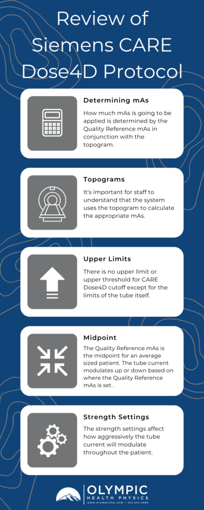
To wrap up, there are several key elements to consider when using Siemens CARE Dose4D for your patients.
- When using CARE Dose4D, you are using the Quality Reference mAs in conjunction with the topogram to determine how much mAs is going to be applied throughout the patient. This will also determine your image quality and radiation dose, or CDTI, for that specific patient.
- It’s important for staff to understand that that topogram is used by this system to calculate what the mAs should be for the patient.
- Remember that there is no upper limit or upper threshold for CARE Dose4E cutoff except for the limits of the tube itself.
- The Quality Reference mAs is the midpoint for an average sized patient (of 75 kilograms). The tube current is going to modulate up or down based on where that Quality Reference mAs is set.
- The strength settings also can affect how aggressively the tube current will modulate throughout the patient.
Ensuring your equipment is operating properly through an annual CT Physics Evaluation may be the best first step in providing a safe environment for your patients. Our CT Physics Evaluations are designed to be compliant with ACR, TJC, IAC, and State requirements for accreditation and compliance purposes. You can also always reach out to us if you have questions or want more information on why you should partner with us.
